Open Melt - Open Source Melty BrainOpen Melt is an open-source translational drift (aka "melty brain") robotics project developed by Rich Olson for the "Melty B" series of combat robots.In short - a melty brain or translational drift robot spins its entire body, but is still capable of directional control by quickly modulating power to its drive motor(s).
Robots using Open Melt: Death by Translation | MBX | Spinning Tortoise | Berzerker 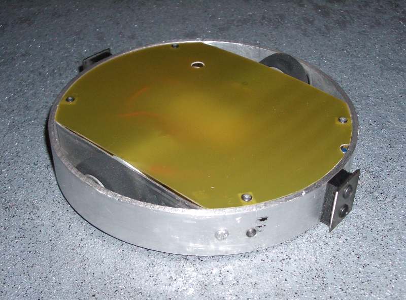 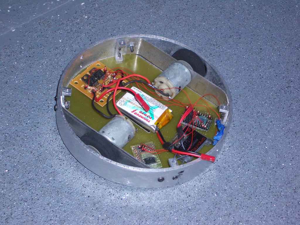 "Melty B" - Antweight (1 lbs) Open Melt Combat Robot (click to enlarge) That data is then used to light up an LED once per rotation - giving the appearance of the "front" of the robot. The user can adjust the heading beacon by moving the remote control left or right. To move - the system turns a motor on when that motor is in the correct position to result in a net movement the direction the robot is intended to go. For example - if the heading beacon is on approximately between 10 o-clock and 2 o-clock it indicates movement will be towards 12 o-clock. Pushing "forward" on the remote then causes the robot to turn on the motor(s) between 6 and 12 o-clock each rotation - the net direction of travel being towards 12 o-clock (this is a simplification - see the 2nd demo video for details). This project uses an Atmel Atmega328 (or 168) and is coded in C using WinAVR.
- Much additional documentation for this project can be found at the beginning of the code Demo Video / Calibration TutorialClick here to skip the overview - and get to the drive demo
Demo Video 2 - 1 vs 2 Motors / More on Translational DriftHardware List (major items)MCU Board:- Pololu Baby Orangutan B-328 (B-168 is also fine - see notes in code on earlier non-"B" versions) - Other Atmel 168 / 328 boards should work - however may require additional hardware / code changes - Starting with a naked Atmega chip isn't recommended unless you really know what you are doing - Project compiles to about 9k - so get a 16k or better chip.
Accelerometer:
NPN Darlington transistor(s) to drive motor(s):
Some kind of motor(s) / wheel(s)
A heading LED
Brushless Motor / Controller Option:
Example Schematic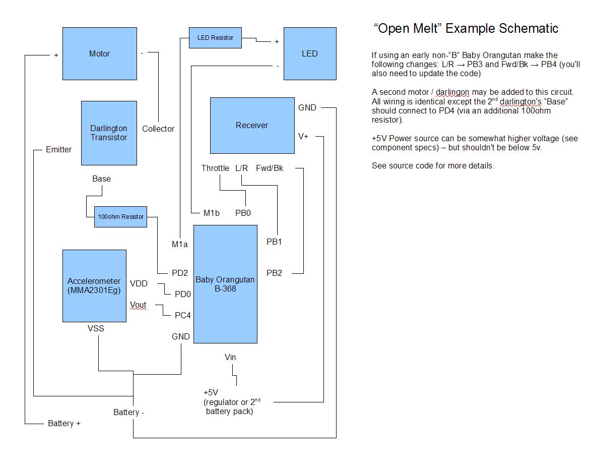
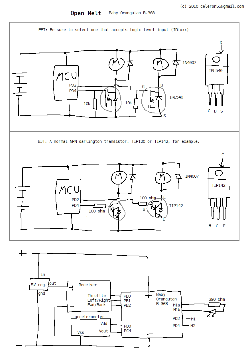
Alternate Schematic Drawing by Perttu Ahola (FETs or Darlington)
|